-
Step 1: Export a neutral 3D format and reopen it
-
Step 2: Set the origin, axis directions, and units before exporting
-
Step 3: Remove hidden solids and duplicate bodies
-
Step 4: Define tolerances in the drawing or PMI
-
Step 5: Think about tool access and workholding
-
Step 6: Spell out material, starting stock, and surface finish
-
Step 7: Send a PDF drawing or complete PMI with every revision
-
Common mistakes that trigger a rejection
-
What about DMG MORI machine price, used machines, and VMC choices?
This checklist is for anyone who is about to send CAD files to a CNC machining supplier—or who has already sent one and got back a long list of awkward questions. It covers the seven checks I run before a file goes near a toolpath. You can use it whether you are ordering 1 part or 1,000. The file-prep rules don’t change with order size; the cost of a mistake does.
I’m a quality and brand compliance manager in the precision CNC machine tool industry. I review incoming model and drawing packages before programming—roughly 130 a month, maybe 150, I’d have to check the tracker. In Q1 2024, we sent back 22% of first-time files because the model didn’t match the drawing or couldn’t be used as supplied. The fix wasn’t better CAM software. It was a better intake checklist. This is the checklist I use.
Step 1: Export a neutral 3D format and reopen it
If your supplier asked for STEP, send STEP—AP214 or AP242, not a screenshot, not a lightweight export from a viewer. Reopen the exported file in a separate viewer before you send it. From the outside, exporting STEP looks like one click. The reality is that the file that looks complete on your screen can lose bodies, units, or PMI during export.
Checkpoint: After export, the part length, volume, and origin should match your master model. If you’re using model-based definition, inspect the PMI in the STEP before you send it.
Step 2: Set the origin, axis directions, and units before exporting
This sounds basic, but it causes more first-article failures than any tolerance debate I know. I review files where the origin is in the air, rotated, or hidden behind a solid so the programmer doesn’t know whether to probe a boss or a bore. If the part is symmetric, don’t expect the programmer to guess which face should be the datum. Mark it.
I didn’t always have a formal check for this. It cost us an $18,000 redo in 2022 because the model’s origin was three inches away from the dimensioned drawing origin. The first article measured fine—until we realized it was being measured from the wrong datum.
Also check units. A file modeled in millimeters but shown as inches is a red flag. If you override the export units, distance values change. The drawing and the model should agree.
Step 3: Remove hidden solids and duplicate bodies
What isn’t visible isn’t always absent. Hidden bodies can remain in an export and confuse CAM. Duplicated bodies also distort mass properties, which matters when your quote is based on material weight or stock size.
Send a clean master model, not the working file with 14 versions, old sketches, and reference geometry sitting around. The third time a customer file contained an overlapping body from an earlier design, I added a model-health check to our intake workflow. That check now catches most of these before the file goes to programming.
Step 4: Define tolerances in the drawing or PMI
Here’s something shop-floor people won’t tell you on the first call: “standard tolerance” is not a real specification. A shop will use its default, often ISO 2768-m or a shop-specific +/-0.1 mm / +/-0.005 in. That default may not match what your product needs.
People assume locking down every dimension with tight tolerances makes the part better. What they don’t see is the effect on cost. If you set a close tolerance on a non-critical edge, you’re paying for inspection and setup care where you don’t need it. Pick the critical features—mating bores, sealing faces, sliding fits—and call out only those.
Step 5: Think about tool access and workholding
Your model has a sharp internal corner. It looks clean in CAD, but a standard end mill can’t cut a true 90-degree internal corner. You can change the corner design, use a smaller tool and lose rigidity, or move to wire EDM. The drawing needs to reflect that reality.
This is where machine specification matters too. You might choose a VMC 8527 or another vertical machining center because its work envelope fits your part. That doesn’t tell the programmer whether the spindle can reach a rear face, whether a right-angle head is needed, or how the part will be held. If the file has no setup notes, ask before requesting a cycle-time quote.
Step 6: Spell out material, starting stock, and surface finish
“Aluminum” is not enough. I need the alloy condition, starting stock dimensions, and whether your supplier should include material in the quote. Same for surface finish: say “32 Ra” or “0.8 µm Ra,” and identify the face that matters. A note that says “no scratches” is not a finish spec.
I’ve seen parts machined beautifully and rejected because the order said “stainless steel” while the drawing called for a passivated finish. A few words on the drawing changed the whole process and added days to the schedule. Oh, and I should add: the customer had signed the approval drawing. We owned the miss too, but the file was incomplete.
Step 7: Send a PDF drawing or complete PMI with every revision
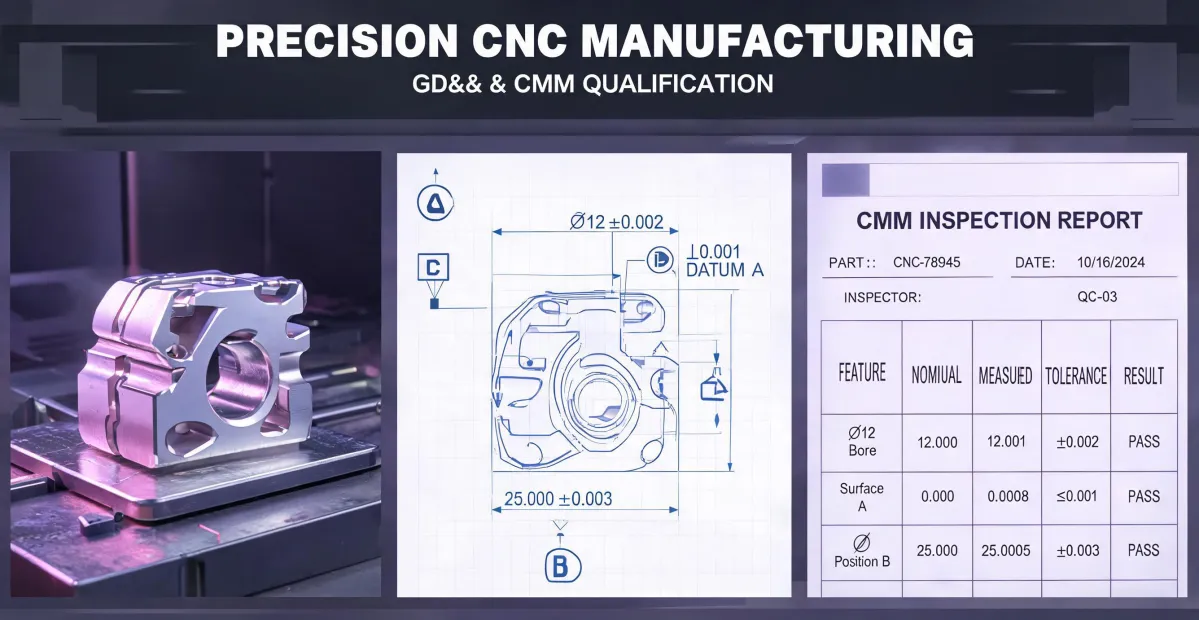
This is the step most people ignore. A 3D model is the best way to describe geometry, but a PDF remains the clearest way to show revision level, origin location, datum references, and which notes override the model.
If you’re fully paperless, your PMI needs to be complete and standards-based. If you are not sure the STEP carries your PMI correctly, send a PDF as well. The most common failure is the opposite: sending a 2D drawing with no model, or sending a model with no drawing. That’s how revision mistakes start.
If the model file says Final_v9 and the PDF says Final_v8, stop. That is a red flag, not a small inconvenience.
Common mistakes that trigger a rejection
- Exporting STL instead of STEP. STL is a mesh, not a CAD file for precision machining.
- Leaving hidden solid bodies or duplicated geometry in the export.
- Setting tolerances only in inessential callouts and leaving critical mating surfaces undefined.
- Changing the model after a quote was issued without sending a new revision.
- Sending the native file when the supplier already asked for a neutral format.
What about DMG MORI machine price, used machines, and VMC choices?
A lot of buyers ask “what is the DMG MORI CNC machine price?” before they have a final CAD package. That makes sense: the machine is the big line item. But in my experience, the more expensive surprise is a bad file. Price matters, but machine value depends on options, service, software support, and how well the machine fits your part mix.
If you find a used DMG MORI CNC machine for sale, don’t let the lower price override the digital workflow audit. Ask for the control software version, calibration history, and a test part cut from the exact model you plan to run. If a seller won’t engage with your CAD file, that’s a sign the post-purchase relationship will be painful.
The specific vertical machining center you choose—a VMC 8527, a newer 5-axis machine, or something else—doesn’t change the basic question. Can this machine, plus the available tooling and posts, produce the geometry in your file while holding the tolerances you have defined? Nothing else matters as much.
Bottom line: CAD prep is not the glamorous part of machining, but it is where quality starts. When a supplier asks for a clean STEP, a defined origin, and a model that matches the drawing, they are not being difficult. They are doing exactly what a quality inspector should do.